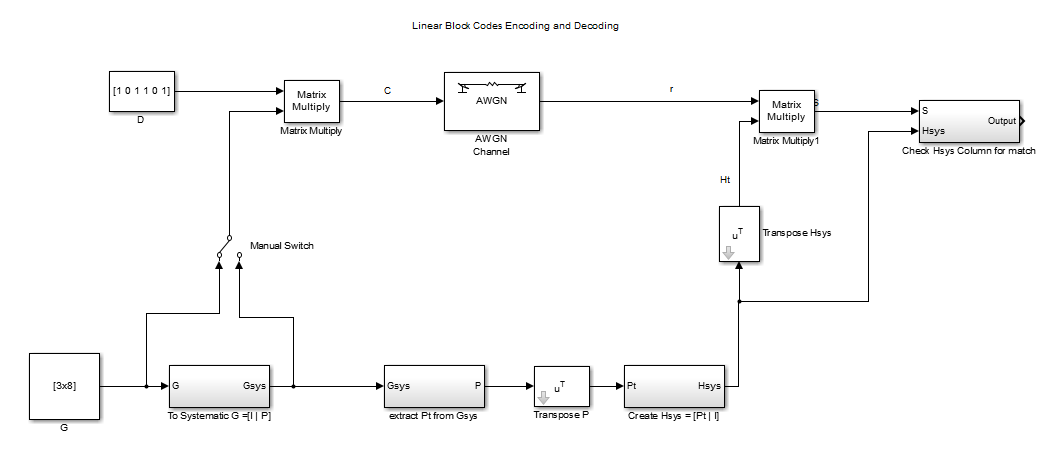
The process of Linear Block encoding and decoding is presented in block diagram form to show the process involved in encoding and decoding.
Linear block code encoder accepts k bits of data blocks and encodes them into n bits of block called codes. The rate of transmission is R = k/n. It is the most simplest form of channel encoding.
The block diagram below illustrates how the channel encoding in the transmitter side and decoding at the receiving side are performed.

At the transmitter encoder, Data to be encoded is multiplied by the Generator Matrix G. The generator matrix may or may not be in systematic form. A Generator Matrix not in systematic form can always be manipulated via appropriate row operation to get systematic form of the matrix. The switch shows that either the non-systematic form of systematic form of G can be multiplied with the data sequence D to get the code words C.
Now the code words C have been generated and the data is protected. These codewords are entered to the communication channel like the AWGN channel. This block has been shown to illustrate that there is a channel that might corrupt the codewords. After passing through the channel we get received code words r.
r = c+e
where, e is the possible error introduced by the channel.
This received signal r is multiplied by the transposed parity check matrix Ht. t means transposed. Ht matrix is created from the generator matrix. The various steps to get Ht from G or the Gsys(depending upon initial G assumption) is also shown in the block diagram.
If G is not in the systematic form, then it is converted to systematic form Gsys via row operation. Then from Gsys knowledge we can know the Parity sub matrix P. We transpose P to get its transposed form Pt. Then from the knowledge of Pt we can get the H matrix and by taking the transpose of H we get Ht.
This Ht is now multiplied by the received code vector r get the Syndrome vector S. S is then analyzed to get information about error and correct error if possible. First if S is zero then there is no error and we can strip off the parity bits to get the message data D. Second if S is non-zero than it indicates that there is error. S vector sequence is compared with the column of Hsys to see if there is any match. If there is match in the jth column for example then the jth bit of S is in error and this is then corrected. Then the parity bits are stripped off from the received vector r to get the message data back.
Linear block code encoder accepts k bits of data blocks and encodes them into n bits of block called codes. The rate of transmission is R = k/n. It is the most simplest form of channel encoding.
The block diagram below illustrates how the channel encoding in the transmitter side and decoding at the receiving side are performed.

At the transmitter encoder, Data to be encoded is multiplied by the Generator Matrix G. The generator matrix may or may not be in systematic form. A Generator Matrix not in systematic form can always be manipulated via appropriate row operation to get systematic form of the matrix. The switch shows that either the non-systematic form of systematic form of G can be multiplied with the data sequence D to get the code words C.
Now the code words C have been generated and the data is protected. These codewords are entered to the communication channel like the AWGN channel. This block has been shown to illustrate that there is a channel that might corrupt the codewords. After passing through the channel we get received code words r.
r = c+e
where, e is the possible error introduced by the channel.
This received signal r is multiplied by the transposed parity check matrix Ht. t means transposed. Ht matrix is created from the generator matrix. The various steps to get Ht from G or the Gsys(depending upon initial G assumption) is also shown in the block diagram.
If G is not in the systematic form, then it is converted to systematic form Gsys via row operation. Then from Gsys knowledge we can know the Parity sub matrix P. We transpose P to get its transposed form Pt. Then from the knowledge of Pt we can get the H matrix and by taking the transpose of H we get Ht.
This Ht is now multiplied by the received code vector r get the Syndrome vector S. S is then analyzed to get information about error and correct error if possible. First if S is zero then there is no error and we can strip off the parity bits to get the message data D. Second if S is non-zero than it indicates that there is error. S vector sequence is compared with the column of Hsys to see if there is any match. If there is match in the jth column for example then the jth bit of S is in error and this is then corrected. Then the parity bits are stripped off from the received vector r to get the message data back.
0 comments:
Post a Comment